Saturday, June 27, 2015

Parallel Resistor and Current Division

Parallel resistor

Resistors are said to be connected together in “Parallel” when both of their terminals are respectively connected to each terminal of the other resistor or resistors. Unlike the previous series resistor circuit, in a parallel resistor network the circuit current can take more than one path as their are multiple nodes. Then parallel circuits are current dividers. 

Equivalent Resistance of two parallel resistors is equal to the product of their resistance divided by their sum.


                      parallel resistance


Equivalent Conductance of resistors connected in parallel is the sum of their individual conductance.


The equivalent conductance of parallel resistors is obtained the same way as the equivalent resistance of of series resistors. In the same manner, the equivalent conductance of resistors in series is obtained just the same way as the resistance of resistors in parallel.


Current Division

Current division allows us to calculate what fraction of the total current into a parallel string of resistors flow though any one of the resistors.

Current Divider 

A current divider circuit is a circuit in which the main current from the power source is divided up in the circuit and, thus, different amounts of current are allocated to different parts of the circuit. 


Mathematical Formula:

If there are more than two branches in parallel, then current can be found according to the current divider formula:

                                   Current division formula

The current that goes through a branch in a parallel circuit is equal to the product of the other branch's resistance and the main current source divided by the total resistance of all the branches. 

Current Divider Formula

If there are more than two branches in parallel, then current can be found according to the current divider formula:

                                             Current Divider Formula

where IX is the current going through a certain branch where you are solving for, IS is the current power source, RT is the total equivalent resistance value of the parallel resistor circuit, and RX is the value of the resistance of the branch for the current for which you are solving.

Series Resistor and Voltage Division

Series Resistor 

Resistors can be connected in series; that is, the current flows through them one after another. The circuit in Figure 1 shows three resistors connected in series, and the direction of current is indicated by the arrow.
 Resistors connected in series.

Voltage division 

   Voltage division is a simple rule which can be used in solving circuits to simplify the solution. Applying the voltage division rule can also solve simple circuits thoroughly. The statement of the rule is simple:

Voltage Division Rule: The voltage is divided between two series resistors in direct proportion to their resistance.


the Ohm's law implies that
v1(t)=R1i(t) (I)
v2(t)=R2i(t) (II)

Applying KVL
v(t)+v1(t)+v2(t)=0v(t)=v1(t)+v2(t) .

Thereforev(t)=R1i(t)+R2i(t)=(R1+R2)i(t) .

Hence
i(t)=v(t)R1+R2 .


Substituting in I and II
v1(t)=R1v(t)R1+R2 ,
v2(t)=R2v(t)R1+R2 .


Consequently
v1(t)=R1R1+R2v(t) ,
v2(t)=R2R1+R2v(t) .

which shows that the voltage is divided between two series resistors in direct proportion to their resistance. The rule can be easily extended to circuits with more than two resistors. For example,

Voltage Division among four resistors
  v1(t)=R1R1+R2+R3+R4v(t) ,
v2(t)=R2R1+R2+R3+R4v(t) ,
v3(t)=R3R1+R2+R3+R4v(t) ,
v4(t)=R4R1+R2+R3+R4v(t) .

The voltage division rule can be used solve simple circuits or to simplify solving complicated circuits. 

Saturday, June 20, 2015

Nodes, Branches and Loops


  Nodes, Branches and Loops

Interconnection of some elements is an electrical circuit., we discussed the path of circuit to fully understand the connections.We, therefore, tackled this week about nodes, branches and loops in the circuit.

  • Branch - represents a single element such as a voltage source or a resistor.
    The circuit figure  contains five elements so it has five branches in the circuit.
  • Node -  is the point of connection between two or more branches.
The different colors in the diagram represents different nodes.
Loop -  is any closed path in the circuit. It starts at a node passing through a set of nodes and returning to the starting node without passing through any node more than once.
An example of a loop.  

KIRCHOFF'S LAW
However, sometimes in complex circuits such as bridge or T networks, we can not simply use Ohm’s Law alone to find the voltages or currents circulating within the circuit. For these types of calculations we need certain rules which allow us to obtain the circuit equations and for this we can use Kirchoffs Circuit Law.

Kirchoff's Two Basic Laws:

  • Kirchoff's Current Law(KCL) 

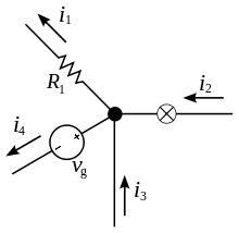
    This is Kirchoff's first law. The sum of all currents that enter an electrical circuit junction is 0. When the currents enter the junction have positive sign and the current that leave the junction have negative sign. 

    It can be stated as:


The current entering any junction is equal to the current leaving that junction. i2 + i3 = i1 + i4   

  • Kirchoff's Voltage Law (KVL) 
This is Kirchoff's second law. The sum of all voltages or potential differences in an electrical circuit loop is 0. it can be stated as:
      • It can be stated as:
The sum of all the voltages around the loop is equal to zero. v1 + v2 + v3 - v4 = 0

BASIC LAWS

These Law's form the foundation upon which Electric Circuit analysis is built.
OHM'S LAW
- This law states that the voltage (v) across a resistor is directly proportional to the current (i) flowing through the resistor. That is,  v α i.
- R is called resistor and has the ability. 

short circuit is a circuit element with resistance approaching zero. V=0, R=0 


An open circuit is a circuit element with resistance approaching infinity. V, R= 


A resistor that obeys Ohm’s law is known as a linear resistor
Conductance (G) - Siemens (S)
- Reciprocal of resistance R, G= 1/R
- Has the ability to conduct current.