Saturday, October 3, 2015

FIRST-ORDER CIRCUIT

FIRST ORDER CIRCUIT


First order circuits are circuits that contain only one energy storage element, and that can, therefore, be described using only a first order differential equation.

The two possible types of first-order circuits are:
  1.  RC (Resistor and Capacitor)
  2.  RL (Resistor and Inductor)
RC and RL circuits is a term we will be using to describe a circuit that has either a resistor and inductor, or, resistor and capacitor.

RC Circuits

An RC circuit is a circuit that has both a resistor (R) and a capacitor (C). Like the RL Circuit, we will combine the resistor and the source on one side of the circuit, and combine them into a thevenin source. Then if we apply KVL around the resulting loop, we get the following equation:

                      v_{source} = RC\frac{dv_{capacitor}(t)}{dt} + v_{capacitor}(t)


RL Circuits


An RL Circuit has at least one resistor (R) and one inductor (L). These can be arranged in parallel, or in series. Inductors are best solved by considering the current flowing through the inductor. Therefore, we will combine the resistive element and the source into a Norton Source Circuit. The Inductor then, will be the external load to the circuit. We remember the equation for the inductor:

                                                  v(t) = L\frac{di}{dt}


If we apply KCL on the node that forms the positive terminal of the voltage source, we can solve to get the following differential equation:


MORE KNOWLEDGE ABOUT FIRST ORDER CIRCUITS:


Saturday, September 26, 2015

INDUCTORS

INDUCTORS

An inductor, is a passive two-terminal electric component which resists changes in electric current passing through it. It consists of a conductor such as a wire, usually wound into a coil. When a current flows through it, energy is stored temporarily in a magnetic field in the coil. When the current flowing through an inductor changes, the time-varying magnetic field induces a voltage in the conductor, according to Faraday's law of electromagnetic induction,which opposes the change in current that created it.

An inductor consists of a coil of conducting wire.


If current is allowed to pass through an inductor, it is found that the voltage across the inductor is directly proportional to the time rate of change of the current. Using the passive sign convention,

where L is the constant of proportionality called the inductance.

Inductance is the property whereby an inductor exhibits opposition to the change of current flowing through it, measured in henrys(H).

The current-voltage relationship is obtained as,


The energy stored is, 


We should note the following important properties of inductor:

1. An inductor acts like a short circuit to DC.
2. The current through an inductor cannot change instantaneously.
3. The ideal inductor does not dissipate energy.
4. A practical, non-ideal inductor has a significant resistive component.

SERIES AND PARALLEL INDUCTORS:

Inductors in Series

Inductors can be connected together in either a series connection, a parallel connection or combinations of both series and parallel together, to produce more complex networks whose overall inductance is a combination of the individual inductors. However, there are certain rules for connecting inductors in series or parallel and these are based on the fact that no mutual inductance or magnetic coupling exists between the individual inductors.

                 inductors in series


The current, ( I ) that flows through the first inductor, L1 has no other way to go but pass through the second inductor and the third and so on. Then, inductors in series have a Common Current flowing through them, for example:

                            IL1 = IL2 = IL3 = IAB …etc.

Inductors in series equation,


Then the total inductance of the series chain can be found by simply adding together the individual inductances of the inductors in series just like adding together resistors in series. However, the above equation only holds true when there is “NO” mutual inductance or magnetic coupling between two or more of the inductors.

Inductors in Parallel

Inductors are said to be connected together in “Parallel” when both of their terminals are respectively connected to each terminal of the other inductor or inductors. The voltage drop across all of the inductors in parallel will be the same. Then, Inductors in Parallel have a Common Voltage across them and in our example below the voltage across the inductors is given as:

                         VL1 = VL2 = VL3 = VAB …etc


In the following circuit the inductors L1, L2 and L3 are all connected together in parallel between the two points A and B. 

inductors in parallel 


Thus,


 Here, like the calculations for parallel resistors, the reciprocal ( 1/Ln ) value of the individual inductances are all added together instead of the inductances themselves. But again as with series connected inductances, the above equation only holds true when there is “NO” mutual inductance or magnetic coupling between two or more of the inductors. Where there is coupling between coils, the total inductance is also affected by the amount of coupling.


CAPACITORS

Capacitors

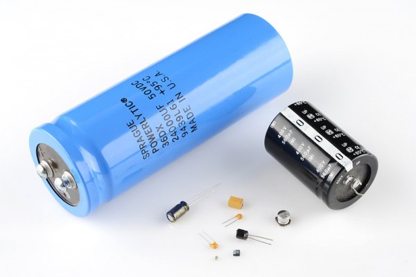
Capacitors are components that are used to store an electrical charge and are used in timer circuits. A capacitor may be used with a resistor to produce a timer. Sometimes capacitors are used to smooth a current in a circuit as they can prevent false triggering of other components such as relays. When power is supplied to a circuit that includes a capacitor - the capacitor charges up. When power is turned off the capacitor discharges its electrical charge slowly.
It is a passive element designed to store energy in its electric field. Besides resistors, capacitors are the most common electrical components. Capacitors are used extensively in electronics, communications, computers and power systems.
A capacitor consists of two conducting plates separated by an insulator.
                      Capacitor variety hour 
 When a voltage source v is connected to the capacitor, as shown in the figure below,
A capacitor with applied voltage.
 the source deposits a positive charge q on one plate and a negative charge - q on the other. The capacitor is said to store the electric charge. The amount of charge stored, represented by q, is directly proportional to the applied voltage v so that
where C, the constant of proportionality, is known as the capacitance of the capacitor.
Capacitance is the ration of the charge on one plate pf a capacitor to the voltage difference between the two plates, measured in farads.
To obtain the current-voltage relationship of the capacitor, we take the derivative of both sides.
 Differentiating both sides of equation.
The voltage-current relation of the capacitor can be obtained by integrating both sides of the equation above.
or
The energy stored in the capacitor is therefore,
 We should note the following important properties of a capacitor:
1. A capacitor is an open circuit to DC.
2. The voltage on a capacitor cannot change abruptly.
3. The ideal capacitor does not dissipate energy.
4. A real, non-ideal capacitor has a parallel-model leakage resistance.


SERIES AND PARALLEL CAPACITORS: 

When capacitors are connected in series, the total capacitance is less than any one of the series capacitors' individual capacitances. If two or more capacitors are connected in series, the overall effect is that of a single (equivalent) capacitor having the sum total of the plate spacings of the individual capacitors. As we've just seen, an increase in plate spacing, with all other factors unchanged, results in decreased capacitance.


 Thus, the total capacitance is less than any one of the individual capacitors' capacitances. The formula for calculating the series total capacitance is the same form as for calculating parallel resistances:


When capacitors are connected in parallel, the total capacitance is the sum of the individual capacitors' capacitances. If two or more capacitors are connected in parallel, the overall effect is that of a single equivalent capacitor having the sum total of the plate areas of the individual capacitors. As we've just seen, an increase in plate area, with all other factors unchanged, results in increased capacitance. 


 Thus, the total capacitance is more than any one of the individual capacitors' capacitances. The formula for calculating the parallel total capacitance is the same form as for calculating series resistances:


 As you will no doubt notice, this is exactly opposite of the phenomenon exhibited by resistors. With resistors, series connections result in additive values while parallel connections result in diminished values. With capacitors, its the reverse: parallel connections result in additive values while series connections result in diminished values.

Saturday, September 19, 2015

Maximum Power Transfer

Maximum Power Transfer

Suppose we have a voltage source or battery that's internal resistance is Ri and a load resistance RL is connected across this battery . Maximum power transfer theorem determines the value of resistance RL for which, the maximum power will be transferred from source to it. Actually the maximum power, drawn from the source, depends upon the value of the load resistance.

                   maximum power transfer theorem
Power delivered to the load resistance,


To find the maximum power, differentiate the above expression with respect to resistance RL and equate it to zero. Thus,


A resistive load in a resistive network will abstract maximum power when the load resistance is equal to the resistance viewed by the load as it looks back to the network. Actually this is nothing but the resistance presented to the output terminals of the network. This is actually Thevenin equivalent resistance as we explained in Thevenin's theorem if we consider the whole network as a voltage source. Similarly, if we consider the network as current source, this resistance will be Norton equivalent resistance as we explained in Norton theorem.
 
 
TO UNDERSTAND MAXIMUM POWER TRANSFER:


Saturday, August 29, 2015

Thevenin's and Norton's Theorem

Thevenin’s theorem

Thevenin’s theorem states that a linear two-terminal circuit can be replaced by an equivalent circuit consisting of a voltage source VTh in series with a resistor RTh, where VTh is the open-circuit voltage at the terminals and RTh is the input or equivalent resistance at the terminals when the independent sources are turned off.


Thevenin's Theorem states that it is possible to simplify any linear circuit, no matter how complex, to an equivalent circuit with just a single voltage source and series resistance connected to a load. The qualification of “linear” is identical to that found in the Superposition Theorem, where all the underlying equations must be linear. If we're dealing with passive components, this is true. However, there are some components which are nonlinear: that is, their opposition to current changes with voltage and/or current. As such, we would call circuits containing these types of components, nonlinear circuits.

Thevenin's Theorem is especially useful in analyzing power systems and other circuits where one particular resistor in the circuit (called the “load” resistor) is subject to change, and re-calculation of the circuit is necessary with each trial value of load resistance, to determine voltage across it and current through it.

In finding the thevenin's resistance RTh, we need to consider two cases:

 
Case 1: If the network has no dependent sources, we turn off all independent sources. Rth is the inpit resistance of the network looking between terminals a and b, as shown below:           

Case 2: if the network has dependent sources. As with Superposition, dependent sources are not to be turned off because they are controlled by circuit variables.


Sample problem: Determine the thevenin’s equivalent  circuit between the terminals A&B For the circuit shown :

Answer:
First we are about to find the thevenin’s resistance. To find the thevenin’s resistance we remove the resistance RL and open circuit the AB terminals. Then we remove the voltage source and short circuit it.


We can easily find the thevenin’s resistance now.
Rth = (5//10 + 3)
Now we have to find the thevenin’’s voltage. For this we remove the load resistance RL.


Applying nodal equation method to point c,
(V-30)/5  + (V-0)/10  = 0

V = 20V

From figure 11.3 you can see that,

VA = VC
VA = VTH
Therefore V = VTH
VTH = 20V

NORTON'S THEOREM

In 1926, about 43 years after Thevenin published his theorem, E. L. Norton, an American engineer at Bell Telephone Laboratories, proposed a similar theorem.

Edward Lawry Norton was an accomplished Bell Labs engineer and scientist famous fordeveloping the concept of the Norton equivalent circuit.
Norton's theorem states that a linear two-terminal circuit can be replaced by an equivalent circuit consisting of a current source IN in parallel with a resistor RN where IN  is the short-circuit current  through the terminals and RN is the input or equivalent resistance at the terminals when the independent sources are turned off.

Norton resistances are equal; that is,


To find the Norton current IN, we determine the short-circuit current flowing from a to b in both circuits.

Original Circuit

Norton Equivalent Circuit

  Since the two circuits are equivalent. Thus,


 Dependent and independent sources are treated the same way as in Thevenin's theorem. Observe the close relationship between Norton's and Thevenin's theorems. Rn = Rth, and: 


 This is essentially source transformation. For this reason, source transformation is often called Thevenin-Norton Transformation.


Sample Problem:
Find the Norton’s equivalent circuit across A-B terminals for the circuit shown.

 Answer:
First we remove the 10Ω resistor and short circuit the terminals A&B. 


The current flowing through the short circuited terminals is called the Norton’s curren IN.
To find the IN we apply nodal equation for point C
(V – 30)/5 + V/10 + V/3 = 0

V = 180/19
Ohms law to 3Ω resistance
I = V/R

IN = (180/19) / 3

IN = 60/19
This is the Norton’s current.
Now we are about to find the Norton’s resistance. Note that this is equal to the thevenin’s resistance also.

RN = (10//5) + 3

RN = 19/3Ω

TO KNOW MORE ABOUT THEVENIN'S AND NORTON'S THEOREM:


Saturday, August 22, 2015

Circuit Theorems

Linearity Property

Linear property is the linear relationship between cause and effect of an element. This property gives linear and nonlinear circuit definition. The property can be applied in various circuit elements. The homogeneity property and the additivity property are both the combination of linearity property.

The homogeneity property is that if the input is multiplied by a constant k then the output is also multiplied by the constant k. Input is called excitation and output is called response here. As an example if we consider ohm’s law. Here the law relates the input i to the output v. 

Mathematically,                                      v= iR

If we multiply the input current  i by a constant k then the output voltage also increases correspondingly by the constant k. The equation stands, 

                                                            kiR = kv

The additivity property is that the response to a sum of inputs is the sum of the responses to each input applied separately.

Using voltage-current relationship of a resistor if

                                                  v1 = i1R       and   v2 = i2R

Applying (i1 + i2)gives
 
                                              V = (i1 + i2)R = i1R+ i2R = v1 + v2

We can say that a resistor is a linear element. Because the voltage-current relationship satisfies both the additivity and the homogeneity properties.

We can tell a circuit is linear if the circuit both the additive and the homogeneous. A linear circuit always consists of linear elements, linear independent and dependent sources.

 Linearity Circuit

A linear circuit is one whose output is linearly related (or directly proportional) to its input.
A linear circuit is a special system whose output is linearly related. Linear circuits are very useful in modeling devices and very well understood. 

To learn more about Linearity:

SUPERPOSITION

  • The superposition theorem eliminates the need for solving simultaneous linear equations by considering the effect on each source independently.
  •  To consider the effects of each source we remove the remaining sources; by setting the voltage sources to zero (short-circuit representation) and current sources to zero (open-circuit representation).
  •  The current through, or voltage across, a portion of the network produced by each source is then added algebraically to find the total solution for current or voltage.
  •  The only variation in applying the superposition theorem to AC networks with independent sources is that we will be working with impedances and phasors instead of just resistors and real numbers.
  •   The superposition theorem is not applicable to power effects in AC networks since we are still dealing with a nonlinear relationship.
  •  It can be applied to networks with sources of different frequencies only if the total response for each frequency is found independently and the results are expanded in a nonsinusoidal expression.
  •  One of the most frequent applications of the superposition theorem is to electronic systems in which the DC and AC analyses are treated separately and the total solution is the sum of the two.
 
When a circuit has sources operating at different frequencies, the separate phasor circuit for each frequency must be solved independently, and the total response is the sum of time-domain responses of all the individual phasor circuits. Superposition Theorem applies to AC circuits as well. For sources having different frequencies, the total response must be obtained by adding individual responses in time domain.


These are some Superposition Technique for sources having different frequencies.

All sources except DC 5-V set to zero


  All sources except 10cos(10t) set to zero


All sources except 2 sin 5t set to zero

vo= v1+ v2+ v3

Consider the following example:


The principle of superposition helps us to analyze a linear circuit with more than one independent source by calculating the contribution of each independent source separately. However, to apply the superposition
principle, we must keep two things in mind:


1. We consider one independent source at a time while all other independent sources are turned off. This implies that we replace every voltage source by 0 V (or a short circuit), and every current source by 0 A (or an open circuit). This way we obtain a simpler and more manageable circuit.

2. Dependent sources are left intact because they are controlled by circuit variables. With these in mind, we apply the superposition principle in three steps.


 Steps to Apply Superposition Principle:
 
1. Turn off all independent sources except one source.

2. Repeat step 1 for each of the other independent sources.

3. Find the total contribution by adding algebraically all the contributions due to the independent sources.


 SUPERPOSITION

Transform a voltage source in series with impedance to a current source in parallel with impedance for simplification or vice versa.


Consider the following example: Calculate the current Io.
  
If we transform the current source to a voltage source, we obtain the circuit shown in Fig. (a).


By current division,


A source transformation is the process of replacing a voltage source vs in series with a resistor R by a current source is in parallel with a resistor R, or vice versa.

Voltage Source Transformation

 We will first go over voltage source transformation, the transformation of a circuit with a voltage source to the equivalent circuit with a current source. In order to get a visual example of this, let's take the circuit below which has a voltage source as its power source:

Voltage Source Transformation


Using source transformation, we can change or transform this above circuit with a voltage power source and a resistor, R, in series, into the equivalent circuit with a current source with a resistor, R, in parallel, as shown below:


Current Source Transformation

We transform a voltage source into a current source by using ohm's law. A voltage source can be changed into a current source by using ohm's formula, I=V/R.

Current Source Transformation

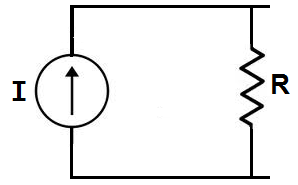
We will now go over current source transformation, the transformation of a circuit with a current source to the equivalent circuit with a voltage source. In order to get a visual example of this, let's take the circuit below which has a current source as its power source:


Current Source Transformation


Using source transformation, we can change or transform this above circuit with a current power source and a resistor, R, in parallel, into the equivalent circuit with a voltage source with a resistor, R, in series, as shown below:


voltage source transformation

We transform a current source into a voltage source by using ohm's law. A voltage source can be changed into a current source by using ohm's formula, V= IR. 
 
 
TO KNOW MORE ABOUT SOURCE TRANSFORMATION: